
After trying to burn my place down one time too many, it’s time to retire my pile of power resistors for testing power supplies in favour of a fancy digital programmable load. Except obviously, I’m going to build it myself, and overengineer it to hell and back.
Update: You might be interested in reading about some updates since this post on the project.
Boiled down to its very core, a programmable load essentially emulates a programmable resistor. Most modern designs use MOSFETs for this, and some hardware (which is usually just an opamp comparing against reference voltage across a current shunt) to implement constant current regulation. A few software smarts can turn that constant current mode into a variety of other useful modes, such as constant voltage, or battery discharge measurements.
What I was after was a pretty basic load that I could pump up to 200W into, at voltages up to at least 24V. There are plenty of nice programmable loads out there around the $400 price point – including used BK Precision and Agilent hardware on eBay – that would have fit the bill. But I’ve been looking for an excuse (any excuse!) to get back into doing embedded stuff for funsies, so I’m going to spend twice as much money (and, if I had any sanity left, some of that, too) to do it myself.
Hardware
From the start, I wanted this project to have a reasonably presentable end appearance. So I started off by trying to find a decent suitable enclosure and settled on the Hammond 1598JBK which is decently spacious inside. This case also drove the decision to separate the hardware into two halves: one digital side, to handle the user interface and external connectivity; and an analog side, which implements the actual load element.
A close second was the Technomet R110 which looks like a proper piece of test equipment. It does seem to cost roughly 3-4x as much as the Hammond enclosure, however.
Analog
This is (probably) the actually interesting board. It contains a pair of extremely beefy MOSFETs and resistors (to measure current) mounted to a neat heatsink, which will in turn have a fan mounted to it. All this is controlled by a bunch of ADCs (to sense voltage/current) and DACs (to drive the current setting) controlled over an isolated I²C bus.
Of note is that this board’s input is completely isolated from the rest of the system. This is accomplished with a pile of optocouplers, a really neat I²C isolator (ADuM1250) and an isolated DC/DC converter to provide its power.
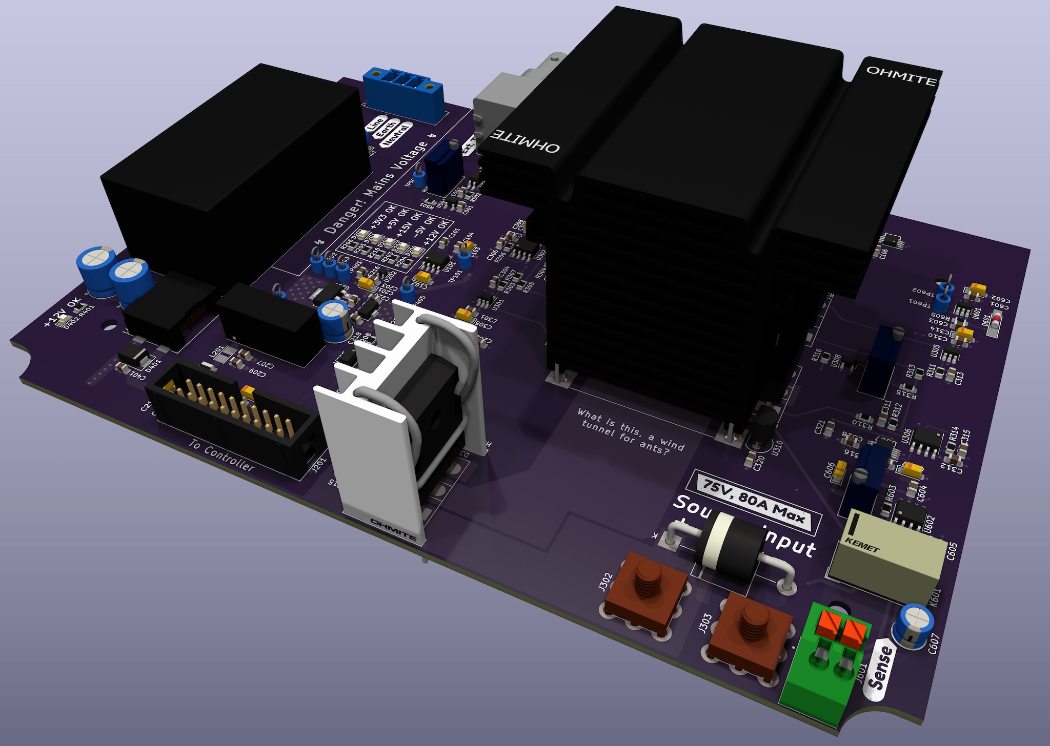
There are also a few odds and ends: protection for the inputs from reverse polarity and overvoltage, a relay to select between internal and external voltage sense, a fan controller for the heatsink, and the hodgepodge of power supplies.
A little bit of leftover space on the board is then used for a mains switching supply. Specifically, this is one of the CUI PSK-20D series: it provides 12V at up to 20W from a pretty wide range of input voltages. The only external components required are a varistor (for protection) and an input fuse. There’s also a JST connector under the supply, to allow using an off-board supply instead.
Digital Board
Obviously, this project needs to be horribly over-engineered, which means there’s gotta be some sort of processor to control everything and provide a pretty user interface. That’s exactly what this board’s sole purpose is.
The star of the show is an ATSAME5x, with up to 1M of flash and 256K of RAM. It’s got a friend in an Ethernet PHY so this thing can get online, of course; and an SPI flash to store persistent configuration data. The rest of the device is connected to one of the many connectors on this board.
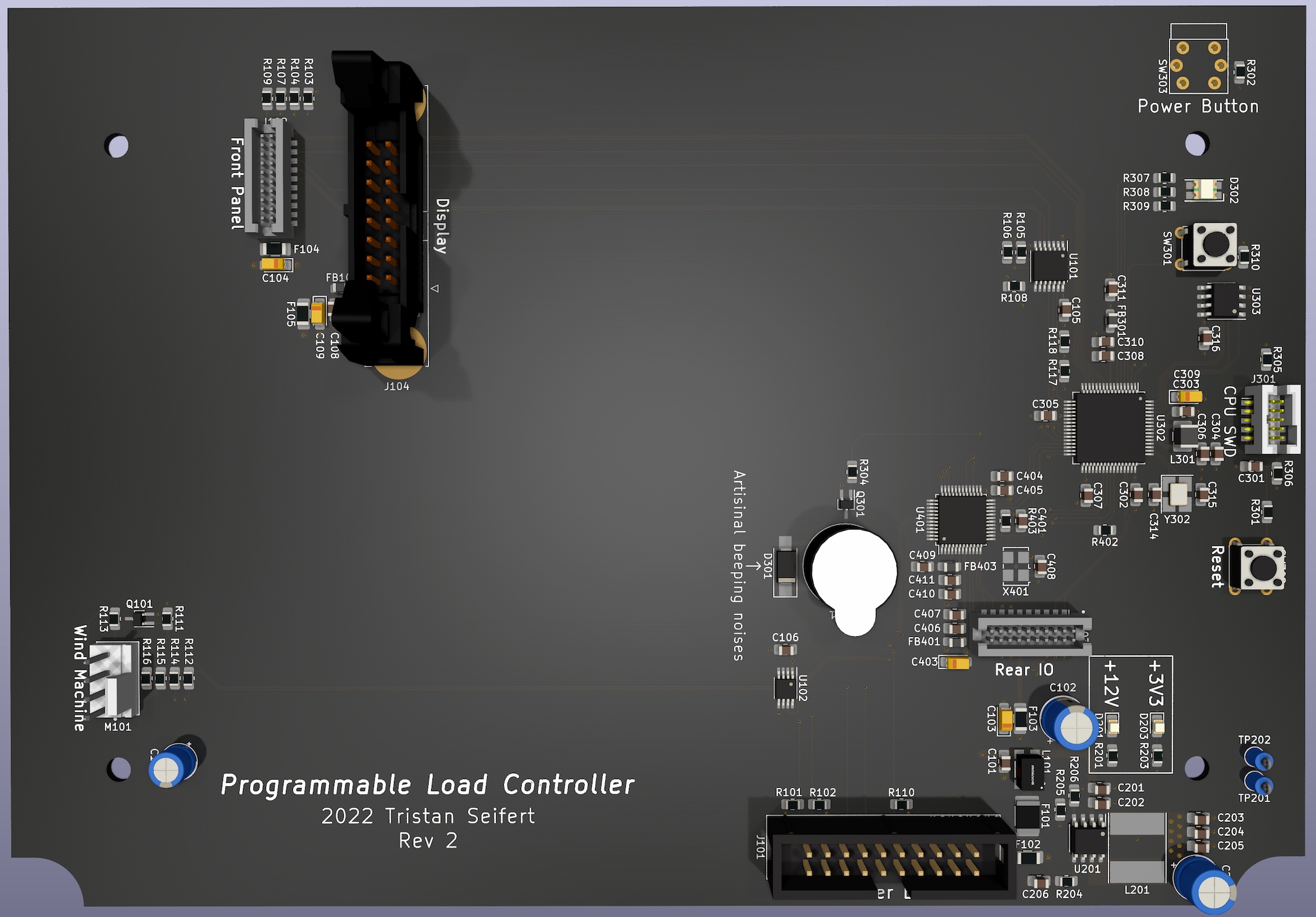
A fan controller provides speed control and monitoring of the case’s rear fan if needed, and a beeper stands by to annoy the shit out of anyone who dares use the device. Lastly, we’ve got a switching regulator to drop the 12V main supply down to the 3.3V preferred by today’s discerning silicon.
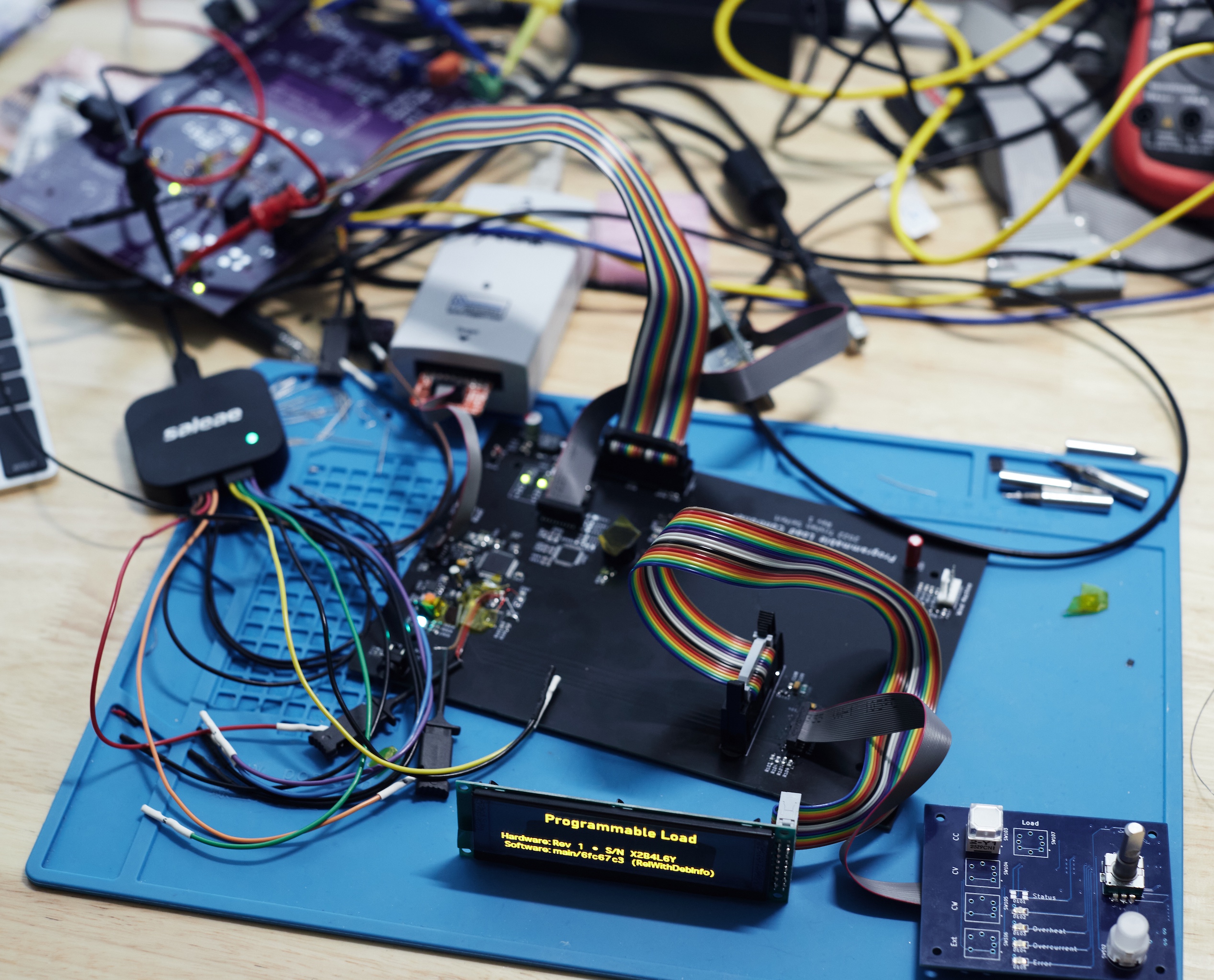
The user interface consists of a 256x64 OLED display connected via SPI on the big ‘ol latching connector. (I had these in my stockpile and wanted to get rid of them. They look cool. That’s the entire reason why.) There’s also a front panel board, connected to a much daintier 1.27mm pin header next to it: this board contains a LED driver and IO expander on an I²C bus. Those are in turn connected to a few mode selector switches, a rotary encoder, and a few indicators.
Lastly, there’s a connector for the rear IO (USB + Ethernet) board and a connector to the analog board. This connector carries the +12V power supply to the board, as well as a few miscellaneous control signals, and a separate I²C bus.
Identifying Hardware
Despite only having one set of “supported” hardware right now, I decided to put a small EEPROM on each of the expansion boards connected to the controller – they all had I²C busses already, so it didn’t add much to the cost. I went with the AT24CS32 type, which has 4Kbit of user-programmable EEPROM, as well as a factory-programmed, unique 128-bit serial number.
The serial number is only used for show, but the user data area of the EEPROM holds a small blob of “atoms” (which is really just tag/length/value) that provide information such as the desired driver, maximum ratings, and so on.
Aside: Microcontroller Choice
Finding a microcontroller to base this design on was probably one of the harder parts of this entire process. The current supply chain issues with semiconductors have made browsing parts distributor websites a basically hopeless endeavour since filtering by “in stock” quickly eliminates the majority of parts.
Instead, I consulted what I have in my parts stockpile1:
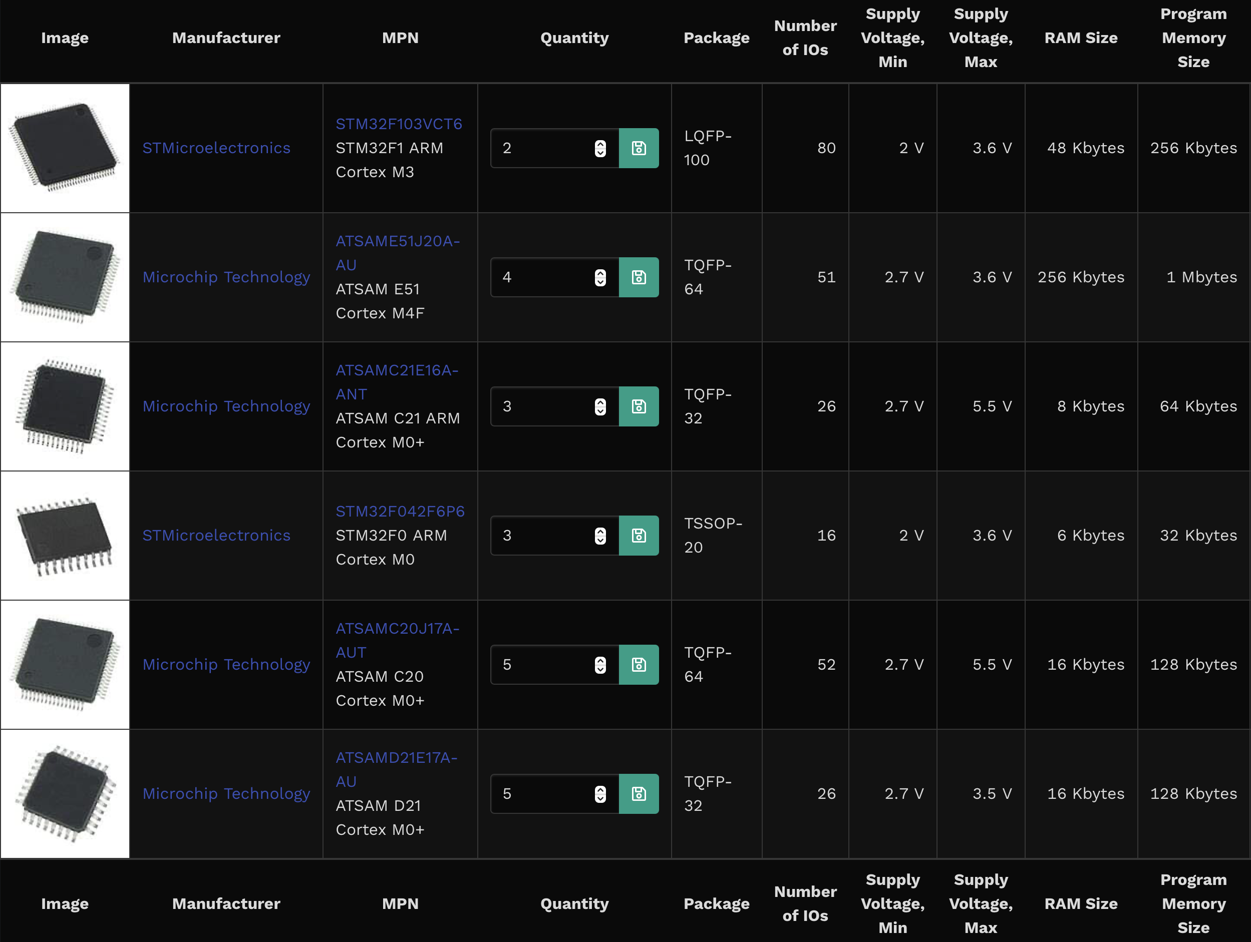
I have absolutely never worked with Atmel/Microchip ARM chips before – but that was all my trusty stockpile had to offer. Overall, I have to say I’m pretty happy with this ATSAME51 chip. The peripherals on the chip are reasonably straightforward to work with, and at the end of the day, it is just a regular ARM Cortex M4. The datasheets in particular have been incredibly useful.
Bodge Time
You’ve probably noticed both these boards are rev 2… that’s for good reason. There were a few fun hardware bugs I had to deal with during the bringup of these boards, which resulted in some lovely bodges.
Thankfully, the worst of the issues was forgetting cutouts for case bosses. The rest ranged from forgotten pull-ups to signals routed to the wrong place, and a reversed I²C bus on the analog board. Also, the analog board would never have worked, since the output current driver opamps could never turn on the MOSFETs… oops.
Software
When starting a new embedded project, the first decision to make is what to base your code on. Is it going to be an open-source ecosystem like Arduino or CircuitPython, or perhaps using the vendor-provided tools?
Turns out, it doesn’t matter, because they are all awful2.
State of the Art
One of the unifying themes in embedded development environments – whether that’s the open source stuff, or provided by the vendors themselves – pretty universally just suck to work with. They are mildly janky at best, and outright hostile to the developer at worst. Thankfully, it’s easy enough to compile the latest llvm from source and get a nice ARM cross toolchain for these little Cortex M chips, so I can for the most part steer clear of them.
The code that ships as part of these environments in the form of libraries or drivers is often times the standard “embedded C” spaghetti mess. Documentation is sparse at best, and the code itself is often filled with subtle, hard to detect bugs. I understand the need for this to be C as the lowest common denominator, but seriously: it’s 2022. We’ve had C++ for decades3 and it kills me to see vendors still pushing straight C.
Most of the examples (and even the provided drivers) also do not play well with an RTOS whatsoever. There’s surely a time and place for the big monolithic major/minor loop construction for embedded firmware, but an ARM core running at 120MHz with 256K of RAM isn’t it.
Embedded Needn’t Suck
Clearly, the solution to everything out there sucking is… yet another alternative solution4. Woohoo! What I’m trying to build here is a generic base for any firmware I write in the future. That way, I can delude myself into thinking I’ll be building more things soon to make this worthwhile.
What I wanted was a simple base to build my code off of, which requires no external dependencies (outside of the toolchain) and did not force me into a particular IDE/editor to write code. As a bonus, a decent debugging experience would be nice.
Turns out, all of that is very much doable… it just meant I would be writing almost all software myself.
What I’ve thrown together is a CMake based project, which combines a few external libraries – ARM CMSIS and FreeRTOS (fetched via CMake’s awesome FetchContent module) – and a homebrewed discount libc, as well as drivers I wrote from scratch. It needs a bit of restructuring to make it truly reusable, especially between different microcontrollers.
The code is a bit messy, but it lets me keep using my existing development workflow (vim/lldb in tmux) which is well worth it. The jankiest part of this entire part is the SEGGER J-Link tools: I haven’t been able to reliably get the SWO trace output working with their GDB server, so I need to run their graphical SWO trace viewer application, then start the GDB server.
Fancy Debugging
I haven’t really bothered with GUI based IDEs (never really been a fan) but decided to give CLion a squiz since they claimed decent embedded support. While it does not work with lldb for some reason, an external GDB did end up getting debugging working.
Importing the project was insanely easy since CLion supports CMake for projects very, very well. I had to do a bit of fumbling around to get it to accept my custom toolchain (specified with a custom CMake toolchain file) but that wasn’t anything too difficult.
This does actually work quite well, especially for debugging. I don’t want to get too attached to this, though, since my education license runs out in a little under a year.
Wrapping Up
Hopefully, I’ll have a few more posts about this project coming soon. The hardware actually exists (and mostly works!) and the core of the software also mostly works. I’m waiting on some second revision boards to show up, and then I need to find the motivation to… actually implement the programmable load part of the software.
For now, there’s a decent chunk of documentation on the project available on my wiki and the hardware/software is available on GitHub as usual.
This is a screenshot from a little project I threw together in February, a way to keep an inventory of the components I have already. I planned to write a post about it back then, but life got in the way… oops. ↩
Obviously many people worked hard to create these tools, and for the average user, they’d much rather just write code rather than wrestle with setting up toolchains or writing their own driver code. Things start getting a bit murky when you want to do something off the beaten path, or dare to want to develop on a non-Windows platform. And most embedded code is… a great example of how to not take advantage of any of the improvements in the discipline of software engineering from the last 25 years. ↩
Even C++11, a major turning point for the language that greatly simplified things, has been supported by embedded toolchains for years now. ↩
There’s a really good xkcd about this. ↩